Login required
You need to be logged in into your account to view downloadable documents.
| Electrical | |
| Model | 422x.09-405-Txx |
|---|---|
| Frequency | 380 – 430 MHz |
| Max. Input Power | 300 W |
| Omni Deviation | < ± 1 dB |
| 3 dB Beamwidth, H-Plane | Omnidirectional |
| Polarisation | Vertical |
| Peak Instantaneous Power (PIP) | 25 kW |
| 3 dB Beamwidth, E-Plane | 8° ±1° |
| Impedance | 50 Ω |
| Gain | 8.7 dBd (10.9 dBi) |
| VSWR | < 1.5:1 |
| Passive Intermodulation | -153 dBc (3rd Order, 2 x Tx @ 43 dBm) (PIM value not guaranteed for N connector version) |
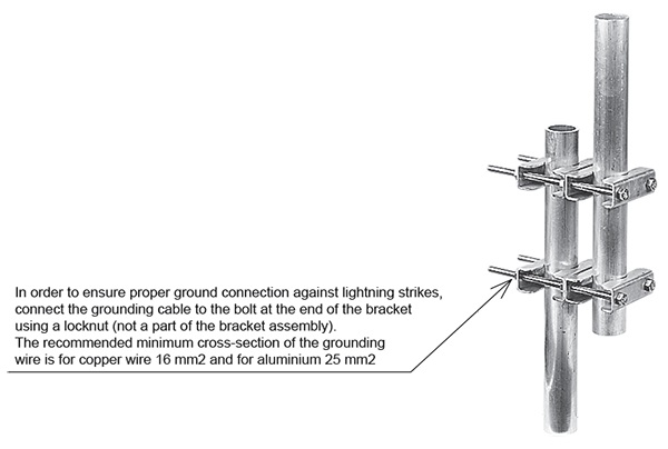
| Lightning Protection | Lightning current handling capability : 200 kA According to EN 62305-1 (Test pulse 10/350 μs) |
| Antistatic Protection | All metal parts DC-grounded (Connector shows a DC-short) |
| Environmental | |
| Operating temperature range | -40 °C to +70 °C |
|---|---|
| Survival Wind Speed | 200 km/h |
| Ingress Protection | IP56 |
| Mechanical | |
| Connection(s) | 7/16 DIN(f), N(f) or 4.3-10(f) |
|---|---|
| Materials | Antenna Base : Aluminium Shroud : GRP tube 53 mm dia. |
| Mounting Section | Al. tube 63.5 mm dia. x 350 mm long |
| Historic Brand | Skymasts |
| Dimensions | 5370 (l) x 53 (dia.) mm / 211.42 x 2.09 (dia.) in. |
| Wind Load | 417 N (160 km/h) |
| Weight | Approx. 13 kg / 28.66 lb. |
| Mounting Bracket | 2141.01.00.00 (up to 120 mm dia.) (Ordered Separately) ETC-250 (50 to 76 mm dia.) (Ordered Separately) |
RADIATION PATTERNS
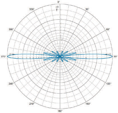
E-Plane | 405 MHz
RADIATION PATTERNS
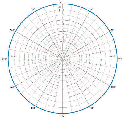
H-Plane | 405 MHz
| Model | Product No. | Frequency | Additional Information | Add To Quote |
|---|---|---|---|---|
|
9 dBd HD omni antenna, low PIM |
4220.09-405-T0 | 380 – 430 MHz | 7/16 DIN(f) ; 0° Electrical Tilt | |
|
9 dBd HD omni antenna, low PIM |
4220.09-405-T2 | 380 – 430 MHz | 7/16 DIN(f) ; 2° Electrical Tilt | |
|
9 dBd HD omni antenna, low PIM |
4220.09-405-T4 | 380 – 430 MHz | 7/16 DIN(f) ; 4° Electrical Tilt | |
|
9 dBd HD omni antenna, low PIM |
4220.09-405-T5 | 380 – 430 MHz | 7/16 DIN(f) ; 5° Electrical Tilt | |
|
9 dBd HD omni antenna, low PIM |
4220.09-405-T6 | 380 – 430 MHz | 7/16 DIN(f) ; 6° Electrical Tilt | |
|
9 dBd HD omni antenna, low PIM |
4220.09-405-T8 | 380 – 430 MHz | 7/16 DIN(f) ; 8° Electrical Tilt | |
|
9 dBd HD omni antenna, low PIM |
4220.09-405-T10 | 380 – 430 MHz | 7/16 DIN(f) ; 10° Electrical Tilt | |
|
9 dBd HD omni antenna, low PIM |
4221.09-405-T0 | 380 – 430 MHz | N(f) ; 0° Electrical Tilt | |
|
9 dBd HD omni antenna, low PIM |
4221.09-405-T2 | 380 – 430 MHz | N(f) ; 2° Electrical Tilt | |
|
9 dBd HD omni antenna, low PIM |
4221.09-405-T4 | 380 – 430 MHz | N(f) ; 4° Electrical Tilt | |
|
9 dBd HD omni antenna, low PIM |
4221.09-405-T5 | 380 – 430 MHz | N(f) ; 5° Electrical Tilt | |
|
9 dBd HD omni antenna, low PIM |
4221.09-405-T6 | 380 – 430 MHz | N(f) ; 6° Electrical Tilt | |
|
9 dBd HD omni antenna, low PIM |
4221.09-405-T8 | 380 – 430 MHz | N(f) ; 8° Electrical Tilt | |
|
9 dBd HD omni antenna, low PIM |
4221.09-405-T10 | 380 – 430 MHz | N(f) ; 10° Electrical Tilt | |
|
9 dBd HD omni antenna, low PIM |
4223.09-405-T0 | 380 – 430 MHz | 4.3-10(f) ; 0° Electrical Tilt | |
|
9 dBd HD omni antenna, low PIM |
4223.09-405-T2 | 380 – 430 MHz | 4.3-10(f) ; 2° Electrical Tilt | |
|
9 dBd HD omni antenna, low PIM |
4223.09-405-T4 | 380 – 430 MHz | 4.3-10(f) ; 4° Electrical Tilt | |
|
9 dBd HD omni antenna, low PIM |
4223.09-405-T5 | 380 – 430 MHz | 4.3-10(f) ; 5° Electrical Tilt | |
|
9 dBd HD omni antenna, low PIM |
4223.09-405-T6 | 380 – 430 MHz | 4.3-10(f) ; 6° Electrical Tilt | |
|
9 dBd HD omni antenna, low PIM |
4223.09-405-T8 | 380 – 430 MHz | 4.3-10(f) ; 8° Electrical Tilt | |
|
9 dBd HD omni antenna, low PIM |
4223.09-405-T10 | 380 – 430 MHz | 4.3-10(f) ;10° Electrical Tilt |
You need to be logged in into your account to view downloadable documents.
Please note that the survival wind speed stated in this specification is based on a static load test simulating a single gust of wind, according to EN 1991-1-4. Continuous flexure of the antenna, over long periods of time in extreme conditions, can cause a gradual deterioration in the structural integrity of the materials; this may result in a reduction of specifications or other failure of the antenna structure.

Click below to sign up for our monthly newsletter to keep informed about our latest products and news from Amphenol Procom.
