No content found
This product doesn’t have any diagrams yet.
| Electrical | |
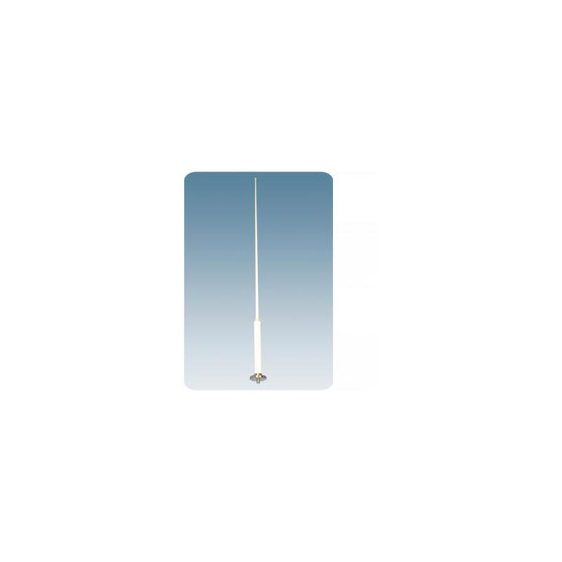
| Model | AIS 2/GPS 4 |
|---|---|
| Frequency | 156 – 162.5 MHz |
| Antenna Type | ½ λ antenna element |
| Max. Input Power | 25 W |
| 3 dB Beamwidth, H-Plane | Omnidirectional |
| Polarisation | Vertical |
| Impedance | 50 Ω |
| Gain | 0 dBd (2.2 dBi) |
| VSWR | < 1.5:1 |
| Environmental | |
| Operating temperature range | -30 °C to +70 °C |
|---|---|
| Ingress Protection | IP66 |
| Mechanical | |
| Wind Area | 0.031 sq. m / 0.33 sq. ft |
|---|---|
| Connection(s) | N(f) |
| Materials | Shroud : Polyurethane coated glass fibre Flange : Chromed brass |
| Colour | Marine white |
| Historic Brand | Amphenol Procom |
| Height | Approx.1350 mm / 53.15 in. |
| Wind Load | 50 N (160 km/h) |
| Weight | Approx. 0.9 kg / 1.98 lb. |
| Mounting | On 30 – 44 mm mast tube using stainless steel clamp type SM-MAS or on deck using DM Mounting Kit |
This product doesn’t have any diagrams yet.
| Model | Product No. | Add To Quote |
|---|---|---|
| Dual Band Antenna for the AIS system | 112000039 |
You need to be logged in into your account to view downloadable documents.
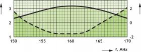
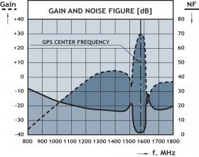
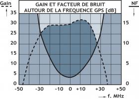
For the VHF band (156 – 162.5 MHz)
VSWR Gain
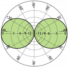
Typical radiation pattern (E-PLANE)
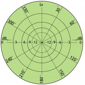
Typical radiation pattern (H-PLANE)
Vertical radiation pattern

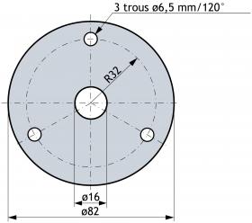
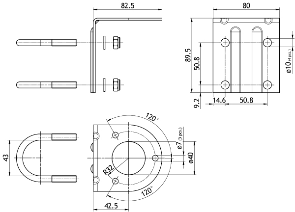
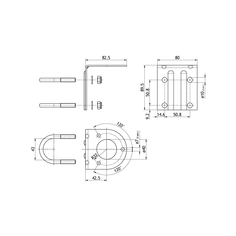
All dimensions are given in mm
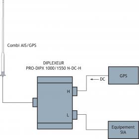
Alternatively, DIPLEXER DIPX 1000/1550-DC-H can be used. Either filter to be ordered separately.
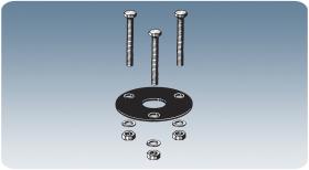
Standard Mounting Kit included.

DM Mounting Kit for Deck Mount to be ordered separately
SM-MAS Mounting Kit for Side Mount and Mast Mount to be ordered separately.
All dimensions are given in mm.
Click below to sign up for our monthly newsletter to keep informed about our latest products and news from Amphenol Procom.
