No content found
This product doesn’t have any diagrams yet.
| Electrical | |
| Model |
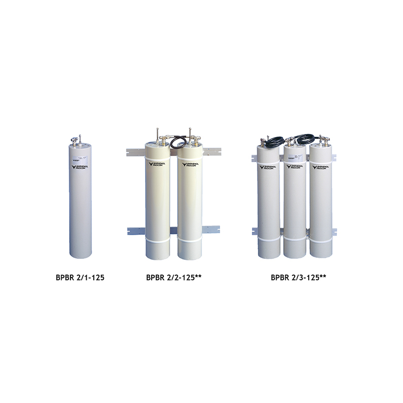
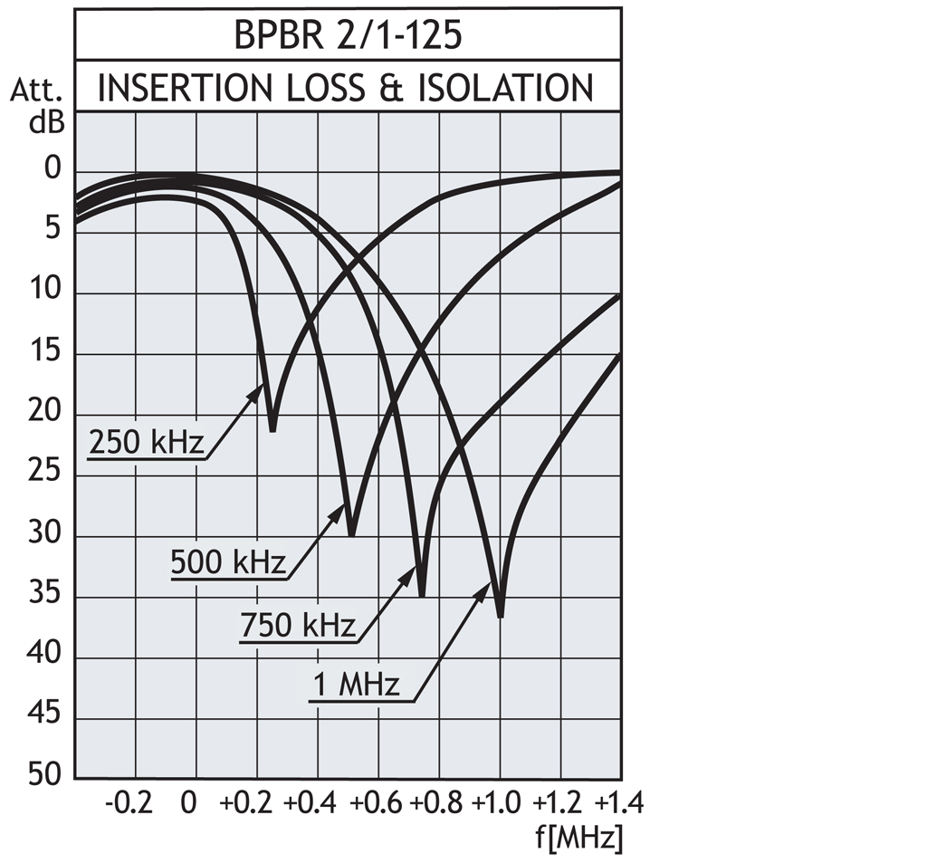
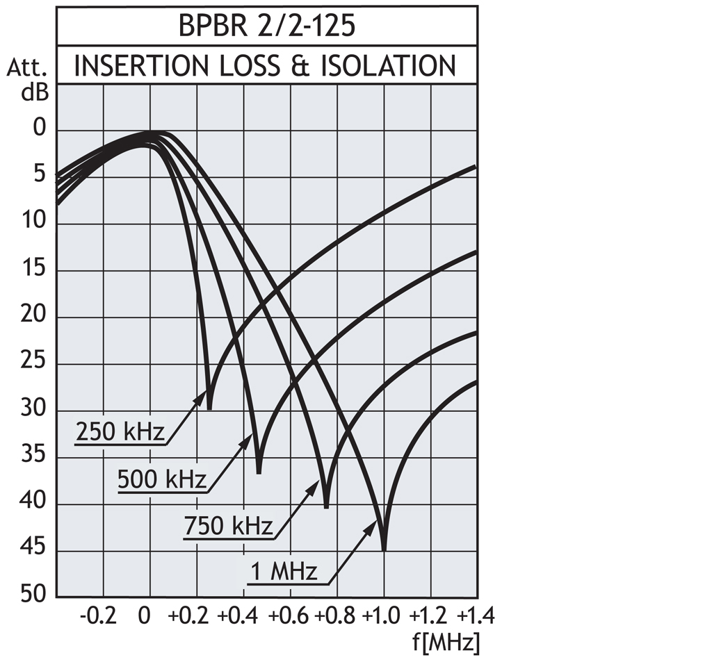
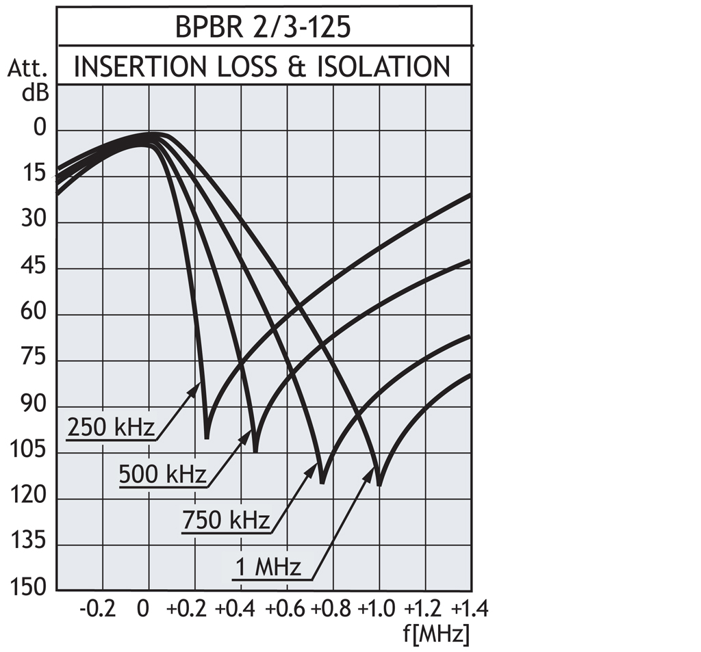
BPBR 2/1-125BPBR 2/2-125BPBR 2/3-125
|
|---|---|
| Frequency |
140 – 175 MHz140 – 175 MHz140 – 175 MHz
|
| Max. Input Power |
250 W250 W250 W
|
| Insertion Loss |
See figure 1 (0.7 dB @ 500 kHz)See figure 2 (1.4 dB @ 500 kHz)See figure 3 (2.1 dB @ 500 kHz)
|
| Impedance |
Nom. 50 ΩNom. 50 ΩNom. 50 Ω
|
| Attenuation |
See figure 1See figure 2See figure 3
|
| VSWR |
< 1.5< 1.5< 1.5
|
| Environmental | |
| Frequency Stability |
Approx. 1.5 ppm / °CApprox. 1.5 ppm / °CApprox. 1.5 ppm / °C
|
|---|---|
| Operating temperature range |
-30 °C to +60 °C-30 °C to +60 °C-30 °C to +60 °C
|
| Mechanical | |
| Connection(s) |
N(f)N(f)N(f)
|
|---|---|
| Dimensions |
ø125 x 600 mm
ø4.92 x 23.62 in.125 x 285 x 600 mm 4.92 x 1.22 x 23.62 in.125 x 425 x 600 mm 4.92 x 16.73 x 23.62 in. |
| Weight |
Approx. 1.9 kg / 4.18 lb.Approx. 4 kg / 8.8 lb.Approx. 6.5kg / 14.33 lb.
|
This product doesn’t have any diagrams yet.
| Model | Product No. | Frequency | Insertion Loss | Add To Quote |
|---|---|---|---|---|
|
BPBR 2/1-125 |
200001081 | 140 – 175 MHz | 0.7 dB @ 500 kHz | |
|
BPBR 2/2-125 |
200000959 | 140 – 175 MHz | 1.4 dB @ 500 kHz | |
|
BPBR 2/3-125 |
200001909 | 140 – 175 MHz | 2.1 dB @ 500 kHz |
You need to be logged in into your account to view downloadable documents.
Other cavity mounting options available:
//amphenolprocom.com/images/PDF/Cavity_Mounting_Options.pdf
Click below to sign up for our monthly newsletter to keep informed about our latest products and news from Amphenol Procom.
