Login required
You need to be logged in into your account to view downloadable documents.

| Electrical | |
| Model |
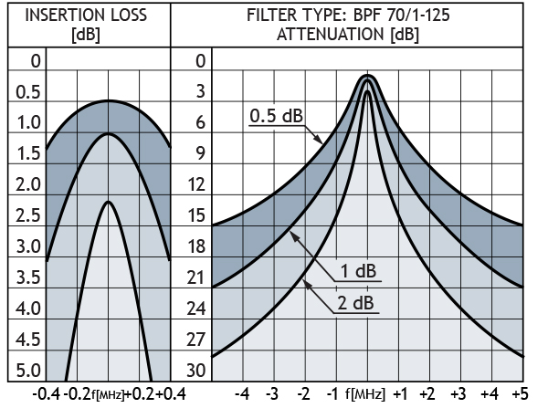
BPF 70/1-125BPF 70/2-125BPF 70/3-125
|
|---|---|
| Frequency |
380 – 470 MHz380 – 470 MHz380 – 470 MHz
|
| Max. Input Power |
300 W @ 0.5 dB IL
125 W @ 2.0 dB IL300 W @ 1.0 dB IL 125 W @ 4.0 dB IL300 W @ 1.5 dB IL 125 W @ 6.0 dB IL |
| Insertion Loss |
Adjustable
0.4 – 2.0 dBAdjustable 0.8 – 4.0 dBAdjustable 1.2 – 6.0 dB |
| Impedance |
50 Ω50 Ω50 Ω
|
| Attenuation |
See diagram 1See diagram 2See diagram 3
|
| VSWR |
< 1.5:1< 1.5:1< 1.5:1
|
| Environmental | |
| Frequency Stability |
1.5 ppm/° C (approx.)1.5 ppm/° C (approx.)1.5 ppm/° C (approx.)
|
|---|---|
| Operating temperature range |
-30 °C to +60 °C-30 °C to +60 °C-30 °C to +60 °C
|
| Mechanical | |
| Connection(s) |
N(f)N(f)N(f)
|
|---|---|
| Historic Brand | Procom |
| Dimensions |
ø125 x 300 mm /ø4.92 x 11.81 in.L: 125 x W: 250 x H: 300 mm /
L: 4.92 x 9.84 x H: 11.81 in.L: 125 x W: 375 x H: 300 mm / L: 4.92 x 14.76 x H: 11.81 in. |
| Weight |
Approx. 1.2 kg / 2.65 lbApprox. 2.7 kg / 5.95 lbApprox. 4.3 kg / 9.48 lb
|
TYPICAL RESPONSE CURVES
| Model | Product No. | Model | Add To Quote |
|---|---|---|---|
|
BPF 70/1-125 |
200000962 | BPF 70/1-125 | |
|
BPF 70/2-125 |
200001049 | BPF 70/2-125 | |
|
BPF 70/3-125 |
200001050 | BPF 70/3-125 |
You need to be logged in into your account to view downloadable documents.
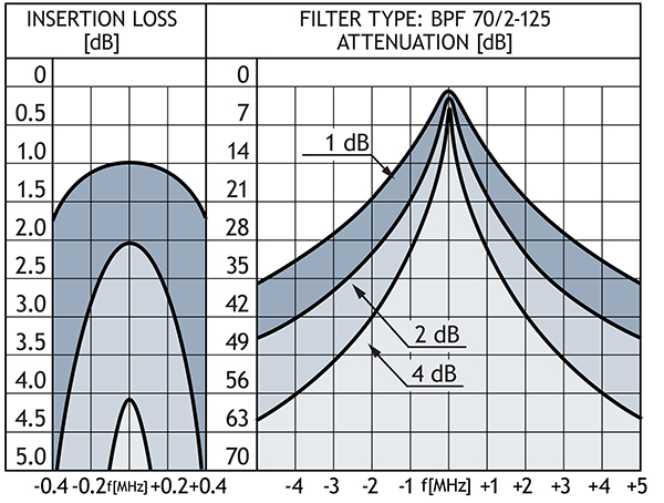
Diagram 2
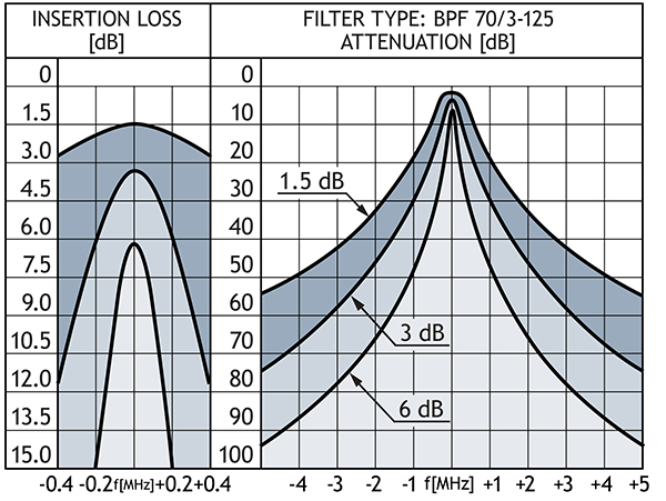
Diagram 3
Click below to sign up for our monthly newsletter to keep informed about our latest products and news from Amphenol Procom.