No content found
This product doesn’t have any diagrams yet.
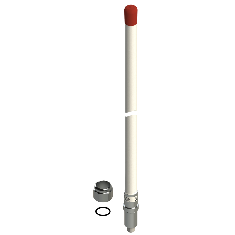
2.7 dBd Gain, Base Station and Marine 900 MHz Antenna for Mounting on Threaded 1” Water Pipe
Find Out MoreOther Files
| Electrical | |
| Model | CXL 900-3/… |
|---|---|
| Frequency | Models within 824 – 960 MHz |
| Antenna Type | Collinear, broad-band |
| Max. Input Power | 100 W |
| 3 dB Beamwidth, H-Plane | Omnidirectional |
| Polarisation | Vertical |
| 3 dB Beamwidth, E-Plane | 36 ° |
| Impedance | 50 Ω |
| Gain | 2.7 dBd (4.9 dBi) |
| VSWR | < 1.5:1 |
| Bandwidth | 70 – 80 MHz |
| HCM Code(s) | HCM000ND00, 018DE25 |
| Environmental | |
| Operating temperature range | -30 °C to +70 °C |
|---|---|
| Ingress Protection | IP66 |
| Mechanical | |
| Wind Area | 0.014 sq. m / 0.15 sq. ft |
|---|---|
| Connection(s) | N(f) |
| Materials | Shroud : Polyurethane-coated glass fibre Mounting bracket : Chromed brass |
| Colour | White (RAL 9003) |
| Height | Approx. 630 mm / 24.80 in. |
| Wind Load | 18 N (160 km/h) |
| Dia. At Top End | 23 mm / 0.9 in. |
| Weight | Approx. 0.4 kg / 0.88 lb. |
| Dia. At Bottom End | 23 mm / 0.9 in. |
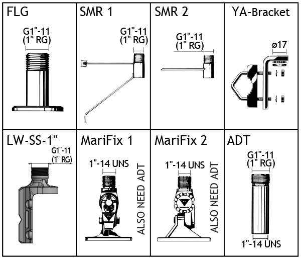
| Mounting | On 1″ RG (G1″ – 11) threaded water pipe or on optional mounting brackets (see accessories ) |
This product doesn’t have any diagrams yet.
| Model | Product No. | Frequency | Add To Quote |
|---|---|---|---|
|
CXL 900-3/l |
110000424 | 824 – 894 MHz | |
|
CXL 900-3/m |
110000456 | 870 – 950 MHz | |
|
CXL 900-3/h |
110000425 | 890 – 960 MHz |
You need to be logged in into your account to view downloadable documents.


Click below to sign up for our monthly newsletter to keep informed about our latest products and news from Amphenol Procom.
