Login required
You need to be logged in into your account to view downloadable documents.
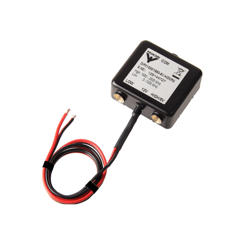
Diplexer for the 0 – 1000 MHz and 1550 – 2500 MHz ranges with built-in GPS antenna power supply
Find Out MoreOther Files
| Electrical | |
| Model | DIPX 1000/1550-5V-H/DCRS |
|---|---|
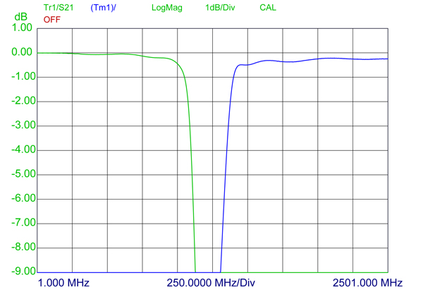
| Frequency | Low port : 0 – 1000 MHz High port : 1550 – 2500 MHz |
| Max. Input Power | 15 W each port |
| Insertion Loss | 0 – 1000 MHz : = 0.8 dB 1550 – 2500 MHz: = 1.0 dB |
| Impedance | 50 Ω |
| DC Input Voltage on DC Cable | 8 – 14 V |
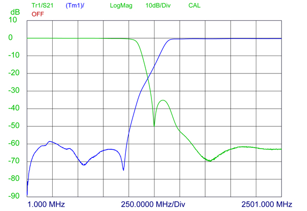
| Isolation | Low to high port: = 45 dB |
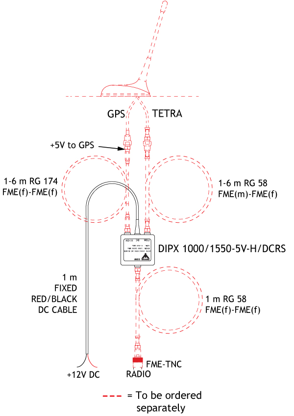
| DC Voltage on High Port | 5 V |
| Max. DC-Current High Port | 200 mA |
| Environmental | |
| Operating temperature range | -30°C to +70°C |
|---|---|
| Mechanical | |
| Connection(s) | LOW : FME(m) HIGH : FME(m) COM: FME(m) DC cable: red (+) / black (-) |
|---|---|
| Historic Brand | Procom |
| Dimensions | 50 x 21 x 50 mm / 1.97 x 0.83 x 1.97 in. |
| Weight | Approx. 0.075 kg / 0.17 lb. |
| DC Cable | Fixed 1 m / 40 in. dual wire red / black |
TYPICAL RESPONSE CURVES FOR 1 dB
TYPICAL RESPONSE CURVES FOR 10 dB
CABLE MOUNTING
| Model | Product No. | Add To Quote |
|---|---|---|
| Diplexer for the 0 – 1000 MHz and 1550 – 2500 MHz ranges with built-in GPS antenna power supply | 200002551 |
You need to be logged in into your account to view downloadable documents.
Click below to sign up for our monthly newsletter to keep informed about our latest products and news from Amphenol Procom.
