Login required
You need to be logged in into your account to view downloadable documents.
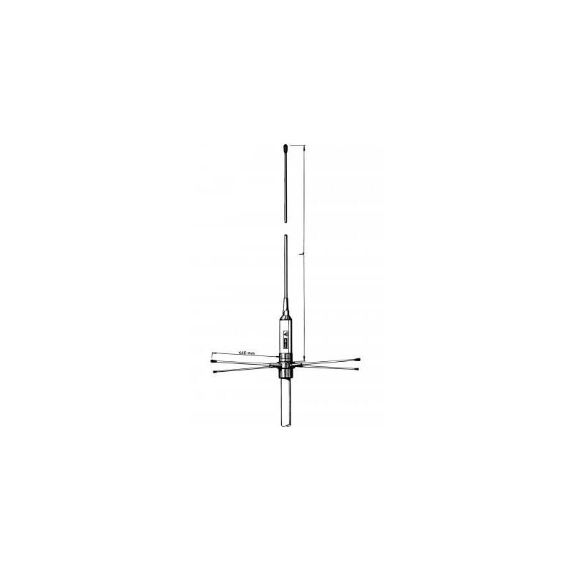
⅝ λ Ground-Plane Base Station and Marine Antenna for the 2 m Band
Find Out MoreOther Files
| Electrical | |
| Model | GP 160 5/8 |
|---|---|
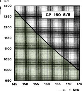
| Frequency | Tunable by cutting within: 145 – 175 MHz |
| Antenna Type | Ground-plane |
| Max. Input Power | 500 W |
| 3 dB Beamwidth, H-Plane | Omnidirectional |
| Polarisation | Vertical |
| Pattern Type | Omnidirectional |
| Impedance | 50 Ω |
| Gain | 1 dBd (3.2 dBi) |
| Bandwidth | 5 – 6 MHz dep. of the cf. freq. (VSWR ≤ 2) |
| Antistatic Protection | All metal parts DC-grounded (Connector shows a DC-short) |
| Environmental | |
| Operating temperature range | -30 °C to +70 °C |
|---|---|
| Mechanical | |
| Wind Area | 0.028 sq. m / 0.30 sq. ft |
|---|---|
| Connection(s) | UHF(f) (fitting PL 259) |
| Materials | Shroud : Polyurethane-coated glass fibre Metal parts : Bright chromed brass |
| Colour | White / bright chrome |
| Historic Brand | Amphenol Procom |
| Height | Approx. 1340 mm / 52.76 in. |
| Wind Load | 35 N (160 km/h) |
| Dia. At Top End | 5 mm / 0.20 in. |
| Weight | Approx. 1.3 kg / 2.87 lb. |
| Dia. At Bottom End | 8 mm / 0.31 in. |
| Mounting | On 27 mm dia. mast tube (¾” water pipe) |
CUTTING DIAGRAM
| Model | Product No. | Add To Quote |
|---|---|---|
| ⅝ λ Ground-Plane Base Station and Marine Antenna for the 2 m Band | 100000108 |
You need to be logged in into your account to view downloadable documents.
The length of the radiator is measured from the upper edge of the head, right above the mounting point of the radials, to the top end of the antenna element. The radials should not be cut.
Click below to sign up for our monthly newsletter to keep informed about our latest products and news from Amphenol Procom.
