No content found
This product doesn’t have any diagrams yet.
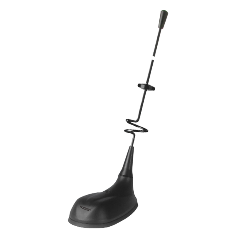
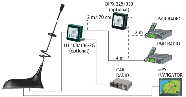
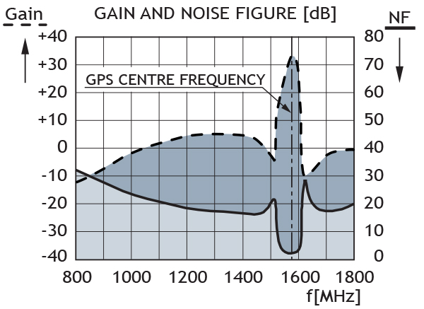
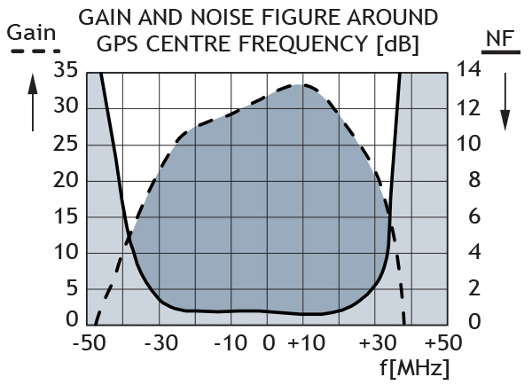
GPS Antenna with WHip for the 160 MHz, 450 MHz and FM Bands
Find Out MoreOther Files
| Electrical | |
| Model | GPS-C MHU 3/FM |
|---|---|
| Frequency | 160 MHz : F.res. within : 140 – 170 MHz 450 MHz : F.res. within : 400 – 470 MHz FM band : 88 – 108 MHz |
| Antenna Type | Triple-frequency antenna |
| Max. Input Power | 25 W |
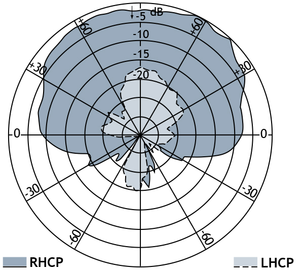
| Polarisation | Vertical |
| Impedance | 50 Ω |
| VSWR | < 1.3:1 @ f.res. |
| Gain (EIA RS-329-1) | 160 MHz : 0 dB (acc. to EIA RS-329-1) 450 MHz : 3 dB (acc. to EIA RS-329-1) |
| Mechanical | |
| Materials | Black-chromed, concial stainless steel Black-chromed brass |
|---|---|
| Colour | Black |
| Historic Brand | Amphenol Procom |
| Antenna Mount Type | Hole Mount |
| Height | Approx. 450 mm / 17.72 in. |
| Max. Roof Thickness | 2.5 mm / 0.10 in. |
| Weight | Approx. 0.06 kg / 0.13 lb. |
| Mounting | On the GPS-Combi mount |
This product doesn’t have any diagrams yet.
| Model | Product No. | Add To Quote |
|---|---|---|
| GPS Antenna with WHip for the 160 MHz, 450 MHz and FM Bands | 132000072 |
You need to be logged in into your account to view downloadable documents.
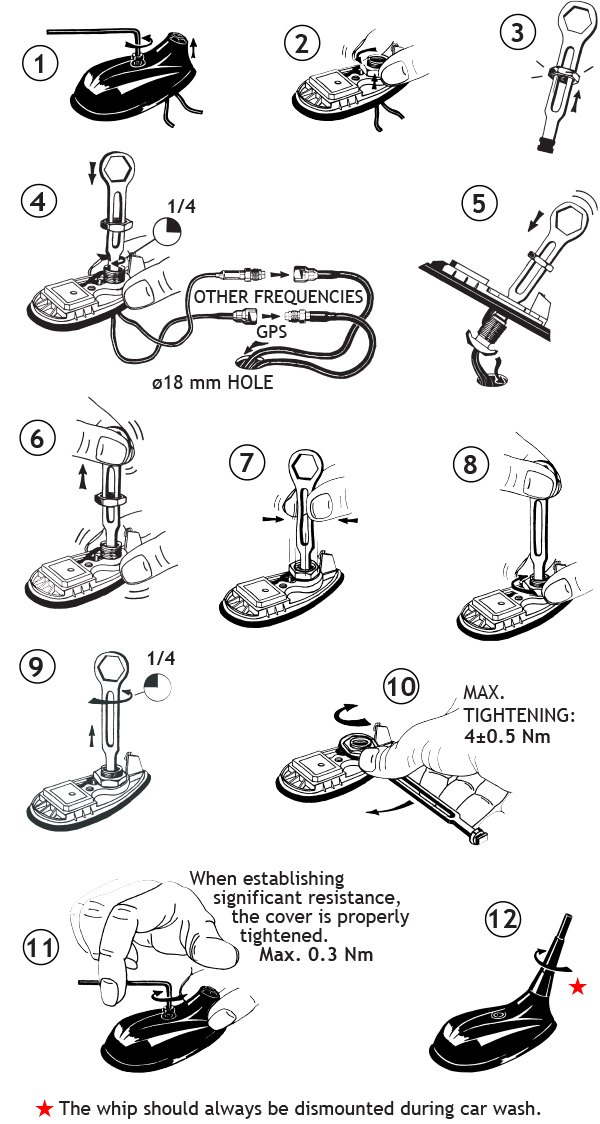
Do not use sealer on rubber gasket or other places.
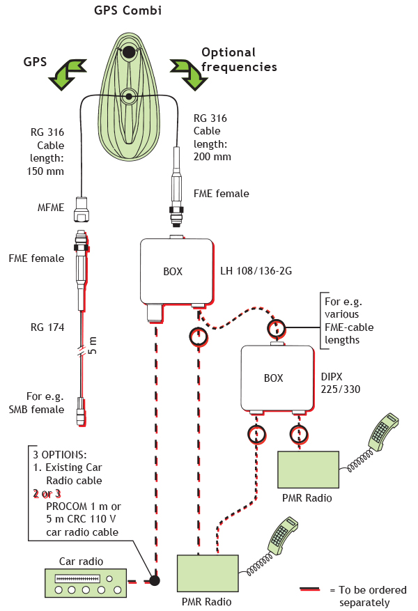
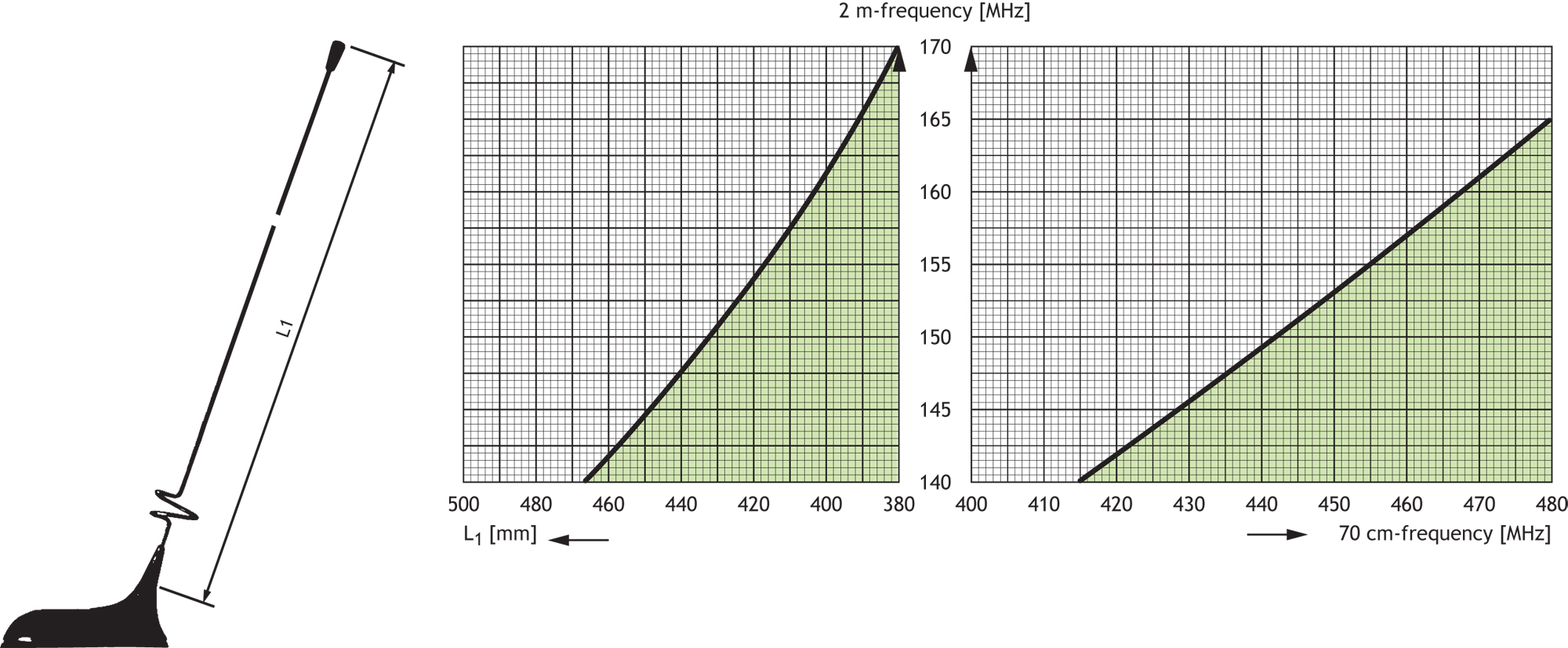
The GPS-C MHU 3/FM cannot be tuned to any pair of frequencies in the two bands. Further, the antenna must be equipped with a different kind of adjustment disc depending on the frequency pair in question.
The antenna can be used without adjustment disc, with a small adjustment disc or with a large adjustment disc. All adjustment disc types are supplied with the antenna.
1. Draw a horizontal line through the point on the vertical axis which corresponds to the 2 m-frequency in question.
2. The drawn horizontal line intersects the shaded area over a certain band of 70 cm-frequencies.
If the 70 cm-frequency to be covered is not included in the shaded area, try another diagram (another adjustment disc type). If the 70 cm-frequency is not covered in any of the diagrams, coverage of the frequency pair in question is not possible using this type of antenna. Please note, however, that taking into account the inherent bandwidth of the antenna (± 2 MHz in the 2 m-band and ± 12 MHz in the 70 cm-band) the combination area may be increased considerably.
For the relevant diagram
3. Read the total length L1 on the left horizontal axis and cut the whip to this length.
4. Locate the 70 cm-frequency in question on the right horizontal axis and read the corresponding length L2 from the curves in the shaded area.

Not every combination of frequency pairs can be delivered. When ordering, please state frequencies between 140 – 170 MHz and 400 – 470 MHz.
Hereby Amphenol Procom declare that the product type GPS-C MHU 3/FM is in compliance with EU Directive 2014/53/EU and
the UK Radio Equipment Regulations 2017 (S.I. 2017 No. 1206).
The full text of the Declaration of Conformity is available at:
https://s3.us-west-2.amazonaws.com/catsy.1080/Declaration-of-Conformity-GPS-C-1.pdf

Use an VSWR-meter to fine-tune the settings
Click below to sign up for our monthly newsletter to keep informed about our latest products and news from Amphenol Procom.
