No content found
This product doesn’t have any diagrams yet.
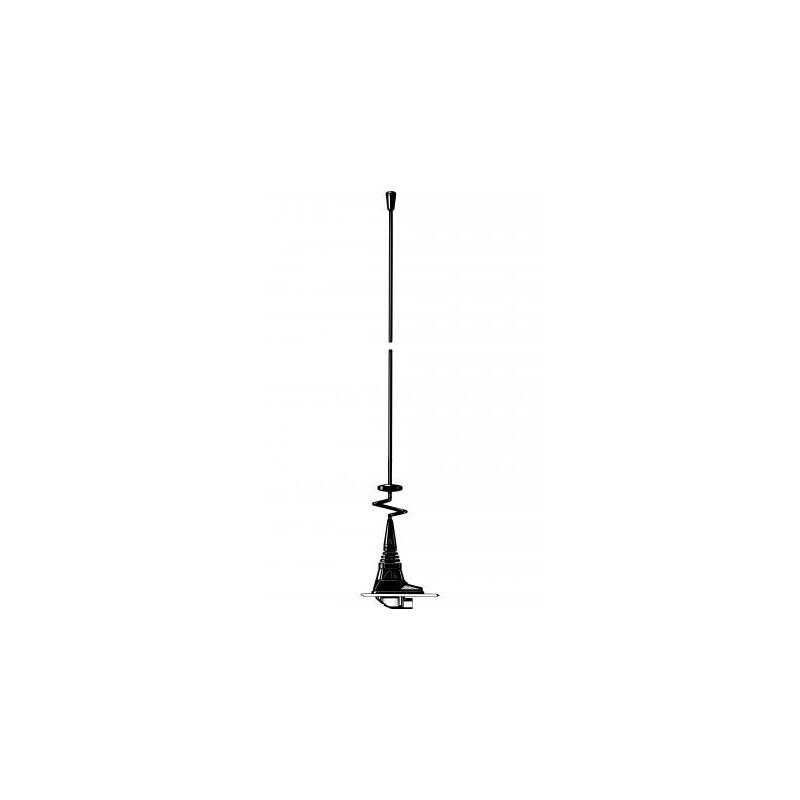
Dual-frequency Mobile Antenna for the 160 and 450 MHz Bands
Find Out MoreOther Files
| Electrical | |
| Model | MHU 3-X, MHU 3-CX, MHU 3-XG |
|---|---|
| Frequency | 160 MHz frequency within : 140 – 170 MHz 450 MHz frequency within : 400 – 480 MHz |
| Antenna Type | Dual-frequency mobile antenna |
| Max. Input Power | 100 W |
| Polarisation | Vertical |
| Impedance | 50 Ω |
| VSWR | ≤ 1.5:1 @ f.res. |
| Bandwidth | 160 MHz : ≥ 4 MHz @ VSWR ≤ 2.0 450 MHz : ≥ 24 MHz @ VSWR ≤ 2.0 |
| Gain (EIA RS-329-1) | 0 – 3 dB |
| Mechanical | |
| Materials | Whip : Black-chromed stainless steel and brass Mount : Black-chromed brass Weather- and shockproof plastics Stainless steel |
|---|---|
| Installation Torque | 4 ±1 Nm |
| Colour | Black |
| Historic Brand | Amphenol Procom |
| Antenna Mount Type | Hole Mount |
| Height | Approx. 560 mm / 22.05 in. |
| Weight | X-version : Approx. 170 g / 0.38 lb. XP4-version : Approx. 305 g / 0.67 lb. CX-version : Approx. 170 g / 0.37 lb. CXP4-version : Approx. 305 g / 0.67 lb. XG-version : Approx. 185 g / 0.41 lb. XGP4-version : Approx. 325 g / 0.72 lb. |
This product doesn’t have any diagrams yet.
| Model | Product No. | Additional Information | Add To Quote |
|---|---|---|---|
|
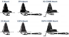
MHU 3-X |
130000770 | X-mount (oblong) with FME-system | |
|
MHU 3-CX |
130000771 | CX-mount (circular) with FME-system | |
|
CXL 70-5C/T-7/s |
Contact_36 | – | |
|
MHU 3-XP4 |
130000776 | XP4-mount (oblong) with 4 m cable and FME-connector | |
|
MHU 3-CXP4 |
130000772 | CXP4-mount (circular) with 4 m cable and FME-connector | |
|
CXL 70-3C/vh |
Contact_37 | – | |
|
MHU 3-XGP4 |
132000412 | XGP4-combi mount (oblong) with 4 m cable, FME-connector and GPS |
You need to be logged in into your account to view downloadable documents.
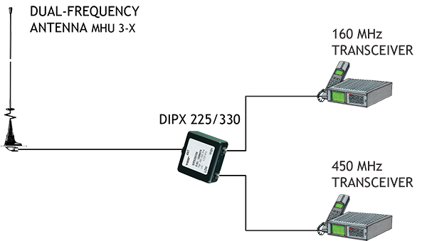
In case of operating two transceivers on one antenna at the same time, a diplexer, type DIPX 225/330 is necessary to complete the system. The tasks of the diplexer are to protect the two receiver inputs from being destroyed by the transmitter in the contrary band, and to ensure a low-loss path between the transceiver and the antenna, which is not loaded by the other branch. For further details please see the separate data sheet on the DIPX 225/330. The diplexer fully covers both bands and, consequently, tuning to specific frequencies is not required.
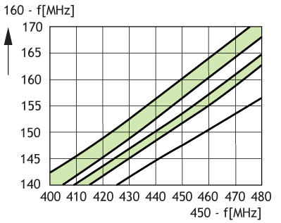
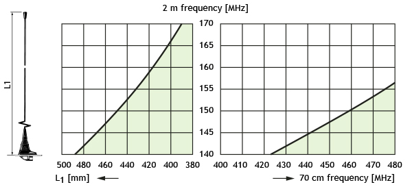
With this type of combination antenna only certain frequenciesfrom the segments 140 – 170 MHz and 400 – 480 MHz can be covered at the same time. The combination area corresponding to “allowable” frequency pairs is shown in the diagram below. However, taking into account the inherent bandwidth of the antenna the combination area may be increased significantly. The antenna can also be delivered factory tuned. Please consult our price list concerning additional charges for adjustment by cutting.
Please refer to the data sheet of each individual mount to find the installation and assembly instructions.
The MHU 3-X cannot be tuned to any pair of frequencies in the two bands. Further, the antenna must be equipped with a different kind of adjustment disc depending on the frequency pair in question. The antenna can be used without adjustmentdisc, with a small adjustment disc or with a large adjustment disc. All adjustment disc types are supplied with the antenna.
Use the diagrams below as follows:
1. Draw a horizontal line through the point on the vertical axis which corresponds to the 160 MHz frequency in question.
2. The drawn horizontal line intersects the shaded area over a certain band of
450 MHz frequencies. If the 450 MHz frequency to be covered is not included in the shaded area, try another diagram (another adjustment disc type). If the 450 MHz frequency is not covered in any of the diagrams, coverage of the frequency pair in question is not possible using this type of antenna. Please note, however, that taking into account the inherent bandwidth of the antenna (± 2 MHz in the 160MHz band and ± 12 MHz in the 450 MHz band) the combination area may be increased considerably.
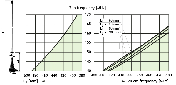
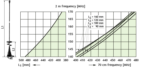
For the relevant diagram:
3. Read the total length L1 on the left horizontal axis and cut the whip to this length.
4. Locate the 450 MHz frequency in question on the right horizontal axis and read the corresponding length L2 from the curves in the shaded area.
Click below to sign up for our monthly newsletter to keep informed about our latest products and news from Amphenol Procom.
