No content found
This product doesn’t have any diagrams yet.
| Electrical | |
| Model | MU 909-XP4/… |
|---|---|
| Frequency | 820 – 940 MHz – covered by two models |
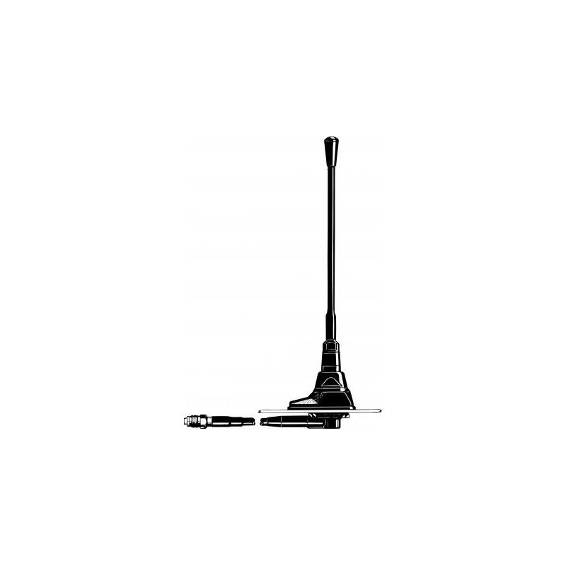
| Antenna Type | End-fed ½ λ dipole mobile antenna |
| Max. Input Power | 25 W |
| Polarisation | Vertical |
| Impedance | 50 Ω |
| VSWR | ≤ 1.2 @ f. res. |
| Bandwidth | ≥ 25 MHz @ VSWR ≤ 1.5 ≥ 50 MHz @ VSWR ≤ 2.0 |
| Gain (EIA RS-329-1) | 2 dB |
| Mechanical | |
| Compliance | ECE R118.02 approved cable |
|---|---|
| Materials | Whip : Polyethylene-covered spring steel wire Mount : Black-chromed brass Weather- and shockproof plastics Surface treated steel |
| Cable | 4 m cable terminated with FME-connector |
| Installation Torque | Max. 3 Nm |
| Colour | Black |
| Historic Brand | Amphenol Procom |
| Height | Approx. 260 mm / 10.24 in. |
| Weight | Approx. 0.2 kg / 0.44 lb. |
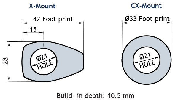
| Mounting | From outside : 21 mm dia. hole From inside : 14 mm dia. hole |
| Mounting Plate Thickness | 0.6 → 5 mm / 0.02 → 0.20 in. |
This product doesn’t have any diagrams yet.
| Model | Product No. | Frequency | Additional Information | Add To Quote |
|---|---|---|---|---|
|
MU 909-XP4/l |
130001227 | 820…890 MHz | Oblong mount with 4 m cable + FME-connector | |
|
MU 909-XP4/h |
130001222 | 870…940 MHz | Same mount as above | |
|
MU 909-CXP4/l |
130001228 | 820…890 MHz | Circular mount with 4 m cable + FME-connector | |
|
MU 909-CXP4/h |
130001223 | 870…940 MHz | Same mount as above |
You need to be logged in into your account to view downloadable documents.
Please note that the MU 909-XP4 type “l”- and “h”-mounts contain matching transformers. Consequently, these special mounts cannot operate with other whip types.
| Model | Frequency/ CELLULAR System | Mount |
|---|---|---|
| Ready-Tuned Models (examples) | ||
| MU 909-XP4/h, EGSM | EGSM | Oblong mount with 4 m cable + FME-connector |
| MU 909-XP4/h, ETACS | ETACS, USA | Same mount as above |
| MU 909-XP4/h, EAMPS | EAMPS, USA | Same mount as above |
| MU 909-CXP4/h, EGSM | EGSM | Circular mount with 4 m cable + FME-connector |
| MU 909-CXP4/h, ETACS | ETACS, USA | Same mount as above |
| MU 909-CXP4/h, EAMPS | EAMPS, USA | Same mount as above |
The MU 909-XP4/… is delivered in two field tunable models but may also be delivered readytuned for CELLULAR systems. When ordering a ready-tuned model, the name of the desired CELLULAR system must be added to the antenna model number.
This antenna is especially designed for installation on non-conducting surfaces as e.g. glassfiber roofs, as can be found on some trucks, busses, transport vans and trains.
The antenna is an end-fed, ½ λ-dipole concept which can be fed in such a way that the antenna does not require a “groundplane” as required by the standard ¼ λ, 5/8 λ or collinear mobile whips. It is useful to note that this antenna type can be used anywhere, where the ground-plane is poor or completely missing, as e.g.: side-mounted on a clamp as a pager antenna on a wall, or mounted at the very edge of a ground-plane without the loss induced by a tilted radiation pattern.
The antenna must be mounted on a horizontal surface. When cleaning the vehicle in car-washing machines, the whip is easily dismounted using a spanner, size 9 mm. The whip is refitted again by screwing it onto the M6 thread stud on the mount and tightening it lightly with the spanner.
A polyethylene-covered, closely spirally wound flat steel-band material causes the whip always to stand erect while at the same time being very flexible.
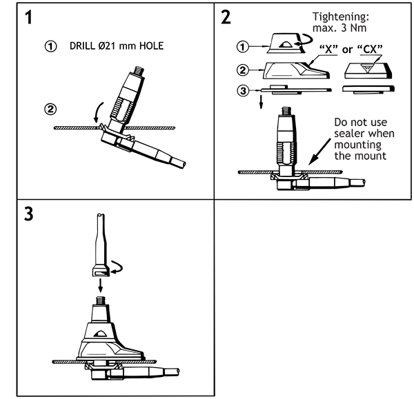
Do not use sealer on rubber gasket or other places.
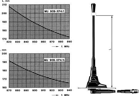
The antenna should always be tuned using an VSWR-indicating device. The cutting diagrams below serve as a guide for this procedure.
To help selecting the correct model for a specific cellular network, please consult the survey of cellular network frequencies under USEFUL DATA in our catalogues.
Click below to sign up for our monthly newsletter to keep informed about our latest products and news from Amphenol Procom.
