No content found
This product doesn’t have any diagrams yet.
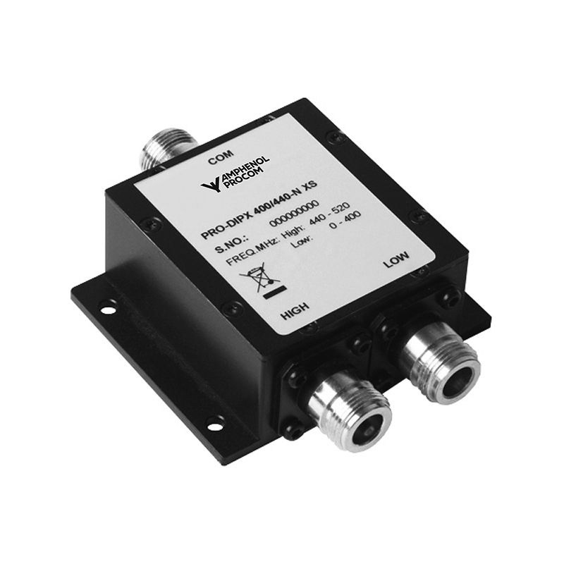
50 W Diplexer for the 0 – 400 MHz and 440 – 520 MHz Ranges
Find Out MoreOther Files
| Electrical | |
| Model | PRO-DIPX 400/440-… XS |
|---|---|
| Frequency | COM – LOW port : 0 – 400 MHz COM-HIGH port : 440 – 520 MHz |
| Max. Input Power | 50 W CW, simultaneously on both HIGH and LOW port |
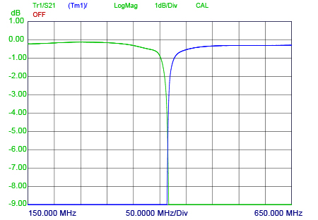
| Insertion Loss | 0 – 400 MHz : ≤ 1.0 dB 440- 520 MHz : ≤ 1.0 dB |
| Impedance | 50 Ω |
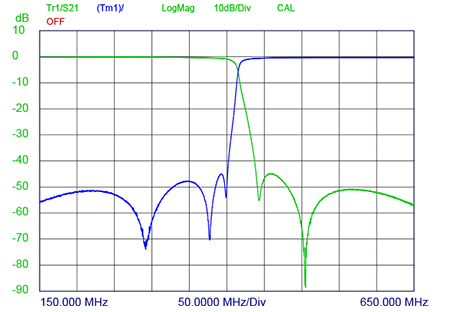
| Isolation | LOW to HIGH port : ≥ 40 dB |
| VSWR | < 1.5:1 |
| Environmental | |
| Operating temperature range | -30 °C to +60 °C |
|---|---|
| Ingress Protection | IP64 |
| Mechanical | |
| Connection(s) | N(f), SMA(f), TNC(f) or BNC(f) (Please see ordering) |
|---|---|
| Historic Brand | Amphenol Procom |
| Dimensions | 103 x 80 x 31 mm / 4.06 x 3.15 x 1.22 in. (incl. connectors and flanges) |
| Weight | Approx. 0.31 kg / 0.68 lb. |
| Mounting | 4.3 mm dia. (4 holes) |
This product doesn’t have any diagrams yet.
| Model | Product No. | Model | Add To Quote |
|---|---|---|---|
|
PRO-DIPX 400/440-N XS |
200002525 | PRO-DIPX 400/440-N XS | |
|
PRO-DIPX 400/440-SMA XS |
200002534 | PRO-DIPX 400/440-SMA XS | |
|
PRO-DIPX 400/440-TNC XS |
200002535 | PRO-DIPX 400/440-TNC XS | |
|
PRO-DIPX 400/440-BNC XS |
200002536 | PRO-DIPX 400/440-BNC XS |
You need to be logged in into your account to view downloadable documents.
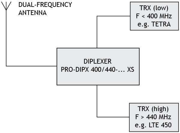
The PRO-DIPX 400/440-… makes it possible to use only one antenna for the operation of two transceivers (one in each range). See the figure. The antenna must be a dual-frequency antenna, i.e. it must be resonant on the actual frequencies in the two bands.
The transceivers may be used independently and will have no degrading influence on each other. Typically, the diplexer is installed next to the transceivers and only one cable is used between the diplexer and the antenna. The diplexer is suitable both for base station and mobile use.
The main tasks of the diplexer are to protect the individual receiver input from being destroyed by the transceiver in the contrary band and to ensure a low-loss path between the transceiver and the antenna which is not loaded by the other branch.
The diplexer can be operated together with any set of transceivers operating within the 0 – 400 MHz and 440 – 520 MHz frequency bands.
Dual-frequency antennas are available for both mobile and base station applications.
Insertion Loss [dB]
Port Attenuation [dB]
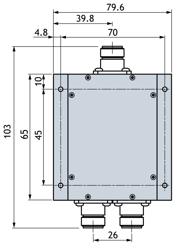
All dimensions are given in mm.
* Temperature on box surface. Adequate cooling to keep max. temperature below +60 ˚;C must be provided.
Click below to sign up for our monthly newsletter to keep informed about our latest products and news from Amphenol Procom.
