No content found
This product doesn’t have any diagrams yet.
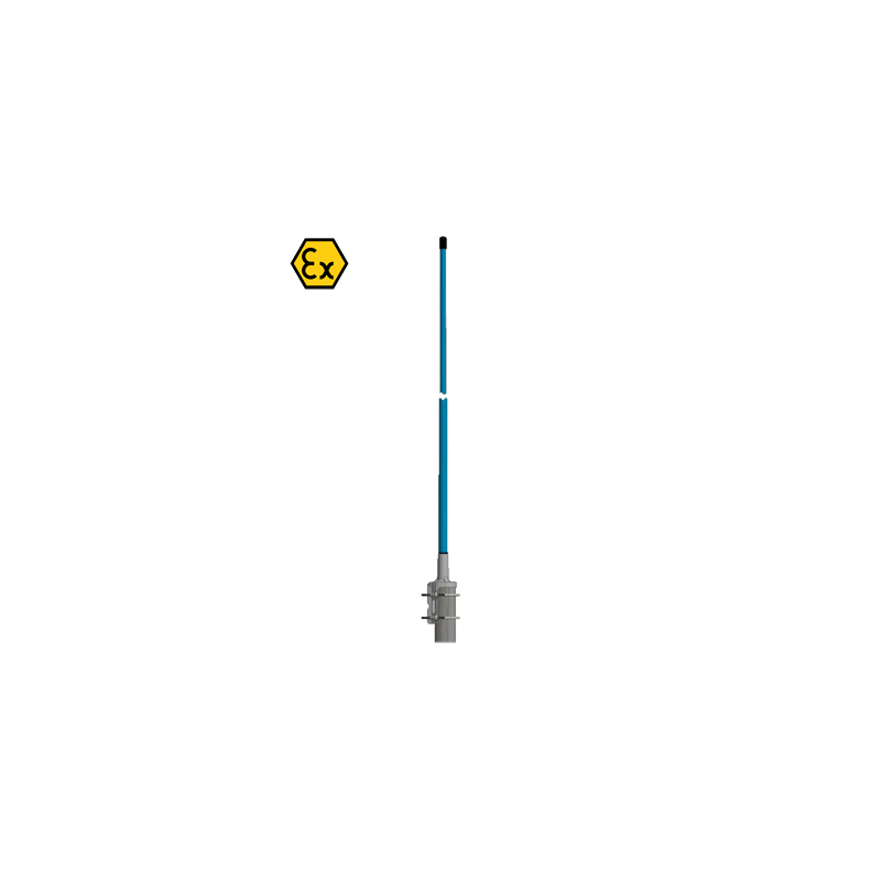
ATEX certified, 3 dBd, Omnidirectional Base Station Antenna for the 380 – 470 MHz Band in Hazardous areas
Find Out MoreOther Files
| Electrical | |
| Model | CXL 450-3LW-SS-Ex |
|---|---|
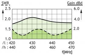
| Frequency | 30 MHz wide frequency segments within 380 – 470 MHz. See ordering designations |
| Antenna Type | Coaxial dipole, broad-banded |
| Special spec. info | Max. RF Input Power due to max. EIRP in ATEX Environment *: Group IIA : 32.6 dBm (1.8 W) Group IIB : 30.3 dBm (1.0 W) Group IIC : 27.8 dBm (0.6 W) |
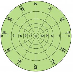
| 3 dB Beamwidth, H-Plane | Omnidirectional |
| Polarisation | Vertical |
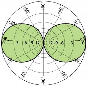
| Pattern Type | Omnidirectional |
| 3 dB Beamwidth, E-Plane | 30 ° |
| Impedance | 50 Ω |
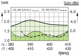
| Gain | 3 dBd (5.2 dBi) |
| VSWR | < 1.5:1 |
| Bandwidth | 30 MHz |
| Antistatic Protection | All metal parts DC-grounded (Connector shows a DC-short) |
| HCM Code(s) | HCM000ND00, 040DE00 |
| Environmental | |
| Operating temperature range | -30 °C to +60 °C |
|---|---|
| Survival Wind Speed | 200 km/h |
| Ingress Protection | IP66 |
| Mechanical | |
| Connector Torque | N(f) : 0.7 – 1.1 Nm |
|---|---|
| Wind Area | 0.029 sq. m / 0.31 sq. ft |
| Materials | Radome : Polyurethane-coated glass fibre Mounting bracket : Stainless acid-proof steel (AiSi 316L) U-bolt and fittings : Stainless steel (AiSi 316) |
| Installation Torque | 3 Nm |
| Colour | Blue (RAL 5015) |
| Historic Brand | Amphenol Procom |
| Height | Approx. 1515 mm / 59.65 in. |
| Wind Load | 33.6 N (160 km/h) |
| Dia. At Top End | 17 mm / 0.67 in. |
| Weight | Approx. 1.55 kg / 3.42 lb. |
| Dia. At Bottom End | 23 mm / 0.91 in. |
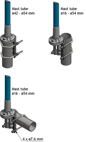
| Mounting | On 16 to 54 mm / 0.63 to 2.13 in. dia. mast tube |
| ATEX Marking | II 3G Ex nA IIC T6 |
This product doesn’t have any diagrams yet.
| Model | Product No. | Frequency | Add To Quote |
|---|---|---|---|
|
CXL 450-3LW-SS-Ex/s |
115000013 | 380 – 410 MHz | |
|
CXL 450-3LW-SS-Ex/f |
115000014 | 406 – 430 MHz | |
|
CXL 450-3LW-SS-Ex/l |
115000015 | 420 – 450 MHz | |
|
CXL 450-3LW-SS-Ex/h |
115000016 | 440 – 470 MHz |
You need to be logged in into your account to view downloadable documents.
| ATEX GROUP | MAX. EIRP POWER | ANTENNA GAIN | MAX INPUT POWER |
|---|---|---|---|
| IIA | 37.7 dBm (6.0 W) | 3 dBd / 5.15 dBi | 32.6 dBm (1.8 W) |
| IIB | 35.4 dBm (3.5 W) | 3 dBd / 5.15 dBi | 30.3 dBm (1.0 W) |
| IIC | 33.0 dBm (2.0 W) | 3 dBd / 5.15 dBi | 27.8 dBm (0.6 W) |
*See the ATEX Product Manual (safety and mounting instructions) and related EU DECLARATION OF CONFORMITY ATEX Directive 2014/34/EU.
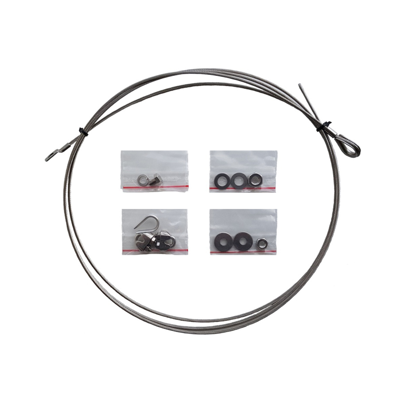
Universal ATEX grounding kit for LW-SS, LW-SS-1” and C mounting bracket
Click below to sign up for our monthly newsletter to keep informed about our latest products and news from Amphenol Procom.
